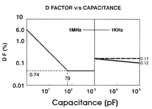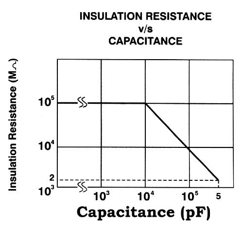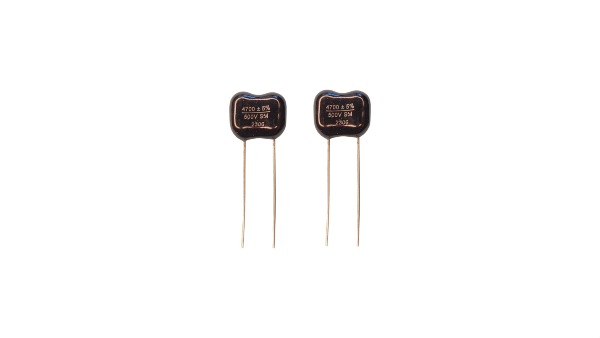
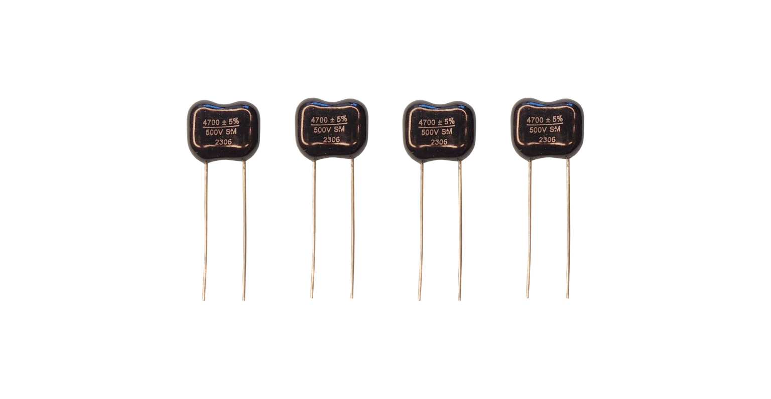
Dipped Mica Capacitors
| Capacitance Range | MIL Equivalent | |||
|---|---|---|---|---|
| Case Style | Commercial | MIL | Straight Leads | Crimped Leads |
| DM5 | 1-390 | ----- | none | none |
| DM10 | 1-470 | 1-390 | CM04 | CM09 |
| DM12 | 1-1500 | ----- | none | none |
| DM15 | 1-1200 | 1-390 | CM05 | CM10 |
| DM19 | 100-8200 | 430-4700 | CM06 | CM11 |
| DM20 | 680-12000 | ----- | none | none |
| DM30 | 5100-20000 | 5100-20000 | CM07 | CM12 |
| DM42 | 16000-100000 | 22000-62000 | CM08 | CM13 |
| VDM16 | 1-1000 | ----- | none | none |
Simic Dipped Mica Capacitors are designed to meet the exacting physical, electrical and environmental requirements of the MIL-C-5 and RS-153 specifications.
It is well known that natural mica is extremely stable against heat. Simic Capacitors are manufactured from selected Indian ruby muscovite mica having optimum electrical characteristics. Silvered mica is made by printing electrodes on mica film with special silver paste. The silvered films are stacked to the desired value interleaved with metal foils for contact. Then the terminals are clamped on to the element. (The terminals are copper clad steel wires finished with a solider coating for good solderability). The clamped unit is either dipped under vacuum in epoxy resin and coated with epoxy powder conformally or dipped in phenolic resin and vacuum impregnated with liquid epoxy resin. The envelope thus formed gives high moisture and heat resistance to the unit. This design ensures high reliability and stability.
Careful selection of raw materials and constant monitoring of all equipment and processes provides an overall uniform level of quality consistent with the stringent requirements of today’s most sophisticated electronic equipment.
Special compact types: Among the many capacitor types manufactured DM5 type features an extremely small size. A single coat available in all the types. The very thin coating assures high installation density. However, for thin types additional moisture proof sealing under high humidity condition.
Capacitance Range
1pF through 100000pF in case styles DM5 through DM42
Voltage Range
50VDCW through 500 VDCW higher voltages on request
Operating Temperature
150°C at full rated voltage
Marking
Simic dipped micas are permanently marked in a manner designed to withstand the environment requirements of the applicable MIL and EIA specifications, as also the permanency and durability requirements of MIL-M-13231.
As a minimum, markings will consist of capacitance in picofarad, capacitance tolerance in percent, and manufacture identifying symbol. Where space does not permit, the capacitance tolerance will be expressed as a single letter.
Parts supplied to the military specification will bear full, or abbreviated, military designation as required by MIL-C-5.
Ordering Code

Style
Indicated by letters CM or DM followed by two digits identifying case size.
Characteristic
Identified by a single letter indicating stability with change in temperature.
Capacitance
Normal capacitance is expressed in pF and is identified by a three number digit. The first two digits represent significant figures. The third digit indicates the number of digits to follow (sometimes referred to as the decimal multiplier). Where a third significant figure is required a four-digit number would be applied. The first three would indicate significant figures.
Leads
All Simic dipped mica capacitors are manufactured with copper-clad steel leads. The copper-clad leads are annealed and manufactured with steel wire SAE 1010 or SAE 1006; having a 30% minimum conductivity copper coating. The leads are finished with 100% tin coating, having a minimum thickness of 0.0001″ (0.00254mm).
Normal production is supplied with straight radial leads. Crimped and/or cut variations are available on order. Capacitors with working voltage of 1000 VDC, 2500 VDC are available on order.
Special Features
Features provided at our customer’s request.
- Metallurgical bonding.
- Thin coat (single dip)for high installation density.
- Crimped and cut leads.
- Crimped and cutleads with tape and reel package.
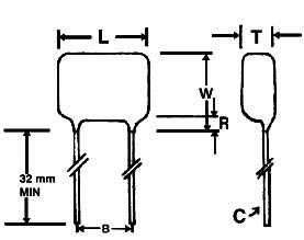
| DIM | DM5 | DM10 | DM15 | DM19 | DM20 | DM30 | DM42 |
|---|---|---|---|---|---|---|---|
| B | 3.05 ±.79 | 3.57 ±.79 | 5.95 ±.79 | 8.73 ±.79 | 11.11 ±.79 | 11.11 ±.79 | 26.99 ±.79 |
| C | #26 (0.4039) | #26 (0.4039) | #22 (0.635) | #20 (0.813) | #20 (0.813) | #18 (1.016) | #18 (1.016) |
| R | 1.98 MAX | 1.98 MAX | 1.98 MAX | 3.18 MAX | 3.18 MAX | 3.18 MAX | 3.18 MAX |
